HOW IT WORKS
FirstLook: How It Works
This section will explain how the FirstLook® sensor works. You can also read the manuals for the ADS ES 100 sensor. To make the understanding easy, we have provided you with the video demonstrations. If you are one of those who prefer visualization than just reading the articles, then it will show you how easy it is for you to use FirstLook® sensors in your day-to-day operations. You can also go through case studies to get a better understanding of the FirstLook® operation.
FirstLook® Theory of Operation:
The FirstLook® sensor looks at the pulse waves generated by the normal operation of an internal combustion engine.
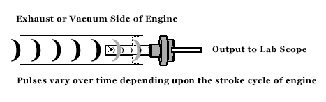
The Engine air flow produces a series of high pressure pulses separated by low pressures. Intake valves and exhaust valves open and close in a specified order with a specified timing. A ‘pulse’ of high pressure air is pushed into the exhaust system every time a cylinder’s exhaust valves open. The sensor detects these pulse waves through either the exhaust or vacuum side of the engine, or through the oil level indicator tube where pressure changes can be caused by ‘blow-by’ around the cylinders and rings. The pressure signature shows the events that occur during the 4-stroke cycle and when in the cycle those events occur. In a perfect engine, the pressure pulses will all look the same and be equally spaced. Engine problems will show in the pressure signature. Abnormal pressure pulses will jump out at you. And the shape of the pulse will tell you what is wrong.
The key to this is FirstLook®’s unique pressure sensor design. This consists of a piezoelectric material in a patented protective housing assembly. The piezoelectric material “measures” the pressures in the air flow in which it is placed.
Why It Works
All materials deform under a load. They compress or bend when the pressure on them increases. They expand or relax when the pressure on them decreases. Some materials, such as rubber, deform easily. Other materials are harder to deform, but they still deform.
Piezoelectric materials produce an electric charge as they are deforming. This electric charge is approximately proportional to the pressure on the material. As the pressure increases, the deformation increases and so does the electric charge.
Piezoelectric materials can only be used to measure dynamic pressures, pressures that are changing. They cannot measure static pressures. The material stops deforming once the pressure becomes static, or constant. Now, the material is no longer producing an electric charge. And the electric charge that was produced bleeds away to zero because of the conductivity of the material. Fortunately for us, air pressures in a running engine are continuously changing.
Internal combustion engines produce a predictable pattern of these pulses which can easily be displayed on most commercially available lab scopes when connected to FirstLook®. This pulse wave is sensed and the voltage is output for display by the lab scope. Any change or irregularity in this predictable pattern can be traced back to problems in the engine. The pulse wave can also be affected by unburned fuel in the exhaust and this abnormality is also detected and displayed. The FirstLook® sensor does not require any external source of power, so you never need to purchase or replace batteries.
Care for your sensor:
Keep water out of the sensors by storing them with the threaded side down. Don’t pull the threaded sensors from hoses, screw them out. Use the nipple adapters to insert into hoses when possible. Use appropriate oil tube attachments to get a good, tight fit. You might have to try several different ones to get a snug fit.
-
- National Guard
- Head Gasket
- Injector Circuit
- Worn Cam and Lifter
CASE STUDIES
- National Guard

- Head Gasket

- Injector Circuit
- Worn Cam and Lifter
A Quality Control Success Story With The Michigan Army National Guard’s Diesel Engine Rebuilding Program
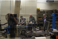
Figure 1. SenX Technology for the Dyno Test Lab at the Michigan National Guard CSMS in Lansing.
"Knowing that we are only shipping to the field, diesel engines in known top condition is a great comfort for all of us at the CSMS Dyno Shop. This development has been a big step forward for us, and use of these tools has become an important part of our standard operating procedure." – Michigan Army National Guard.
The Michigan Army National Guard operates and maintains a very large fleet of heavy diesel equipment. It is imperative that this fleet be kept at a high level of readiness and reliability at all times. The vehicles are stationed at armories distributed around the state and are maintained at a number of strategically located Field Maintenance Site (FMS) centers that support these local armories. When a particular vehicle exhibits mechanical problems requiring extensive engine repair, the problem engine is removed at an FMS and sent to the Centralized Service and Maintenance Site (CSMS) facility where extensive engine rebuilds can be made. A rebuilt or new engine is then sent from a quality controlled inventory at the CSMS for reinstallation at the FMS center.
It is really important that these rebuilt engines be carefully inspected and analyzed to assure that the resulting engine is truly as “good as new” before sending it out to an FMS for replacement in an active service vehicle. To accomplish this, the final step in the CSMS rebuilt engine quality assurance protocol is to place the engine on the CSMS dynamo meter and verify that all of the cylinders, valves, head gaskets, injectors, fuel pumps and all the required mechanical adjustments are “just right” for shipment to the field. The CSMS technical staff, SenX Technology, and Pico Technology have assembled a mechanical testing solution that provides the Michigan Army National Guard a quantum leap in the speed and accuracy of this final testing procedure. A four channel PICO automotive lab scope is used to display the data from two SenX Technology FirstLook ADS ES 100 pulse sensors and one trigger signal simultaneously on a laptop computer screen. One FirstLook sensor is placed in the exhaust pipe to observe valve condition and for comparing compression across the cylinders. The second FirstLook sensor is placed in the oil dipstick tube to monitor the crankcase pressure variations due to blow-by. Optionally a third sensor could be placed in the intake manifold for additional information. The trigger signal is taken from either an electrical signal to the #1 injector or from a piezoelectric sensor placed on the fuel line to the #1 cylinder. This allows the identification of any problem seen in the FirstLook data to be associated with a particular cylinder by consideration of the firing order.
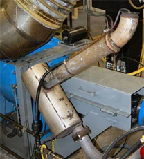
Figure #2a. Picture shows Firstlook sensor secured in exhaust using a copper tube.
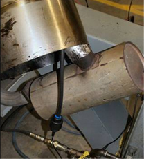
Figure #2b. Picture shows Firstlook sensor with vent hood in place.
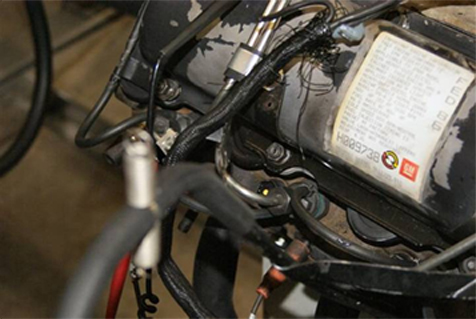
Figure 3. Operational detail showing FirstLook sensor probe over dipstick tube.
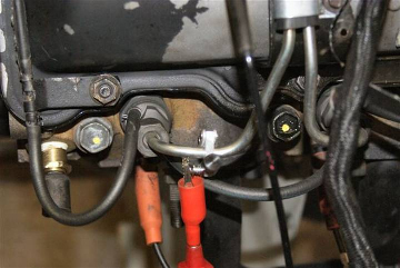
Figure 4. Operational detail showing piezo trigger placement on #1 injector fuel line.
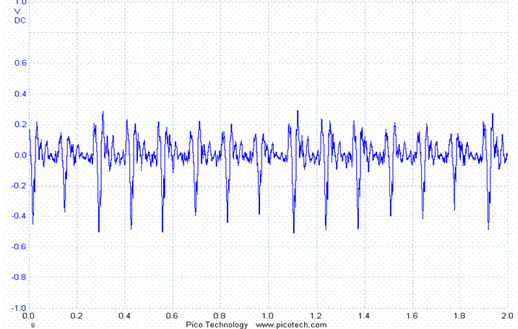
Figure 6. Cold crank on 6 cylinder Cummings diesel engine. Exhaust Waveform is basically uniform showing clearly individual cylinders.
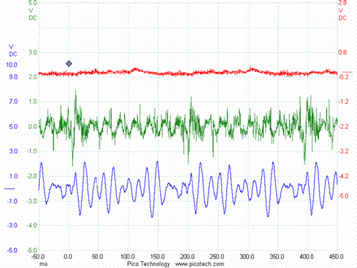
Figure 7. Idle data from exhaust (bottom), crankcase (top) and trigger from a bad engine.
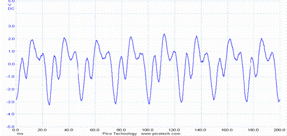
Figure 8. Idle exhaust data from a Cummings diesel engine in good condition. Note the clean repeating waveform.
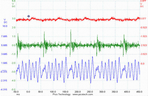
Figure #9. Note the top line which is the crank case pressure fluctuations. This indicates leakage into the crank case of a cylinder when under load.
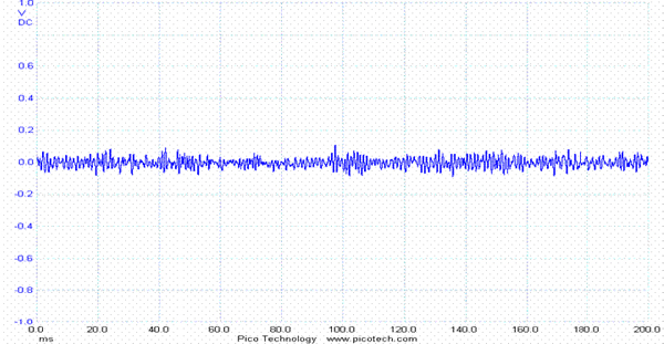
Figure #10. This shows normal crank case fluctuations in a Cummings Engine. Diesel engines will always show a percentage of blow by. As the engine gets old this will increase and can be used to gauge engine condition.
The engine tests are run under three conditions – cold cranking with no fuel at about 300RPM, warm idle at about 750 RPM, and with a braking load at about 1500 RPM. Under all of these conditions, the pulse data from each cylinder should compare virtually identically with all of the others in a well set up and properly assembled engine. A major deviation between cylinders indicates a problem to be diagnostically examined more closely. Typically such an engine must be returned to the shop for repair. On the other hand, if all the data between cylinders is closely comparable, the mechanical condition of the engine is good and it may be confidently placed in the inventory for future installation in the field.
This solution is very economical to implement, and the benefits are so large that payback has been almost immediate. The cost for implementing this solution, assuming a portable or desk mounted PC is available, is less than $4000 for the lab scope and sensors. In the very first weeks of this solution’s operation, several engines, which to outward appearance and from normal testing were suitable for shipment to the FMS for replacements, were found to be faulty and require further work. Stopping even one problem engine from leaving the CSMS would have saved the cost of the testing equipment, and already several engines have been identified and proper corrective actions taken before final QC approval was given.
" that we are only shipping to the field diesel engines in known top condition is a great comfort for all of us at the CSMS Dyno Shop. This development has been a big step forward for us, and use of these tools has become an important part of our standard operating procedure."
For more information on FirstLook Automotive and Diesel Diagnostic Sensors see www.SenXTech.Com
For more information on PICO Technology Automotive and Diesel Diagnostic Oscilloscopes please see www.PICOTech.Com
Here we show a case where the engine integrity is poor and OBD is misleading. A faulty head gasket is the problem. Thanks to Jeff Kogan for this study.
Cylinder Head Gasket.pdf : Click Here
Here we show how to use the Firstlook sensors to identify bad injectors. Thanks to Jeff Kogan of Square One Diagnostics for this write-up!
Injector.pdf : Click Here
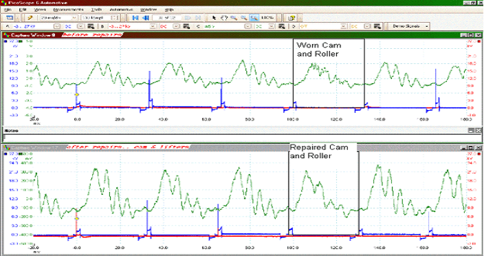
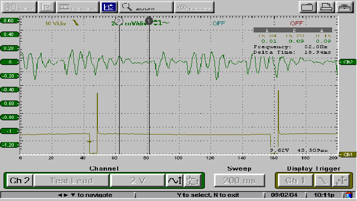
This problem was solved using the FirstLook Sensor on the intake manifold and collecting vacuum waveforms. “This mystery could not be solved without the First Look Sensor hooked up to a Pico Scope and the training and support from Tom Roberts (Autonerdz)” Wilf Breyfogle
2000 GMC Safari van, 221,000 km, 4.3L vortec
Worn cam and lifter : Click Here
-
- National Guard
- Head Gasket
- Injector Circuit
- Worn Cam and Lifter
SenX FirstLook Pulse Sensor Intro 2014
Louie Nelson provides an introduction to the FirstLook® sensor and several ways it can be used to help in diagnosis physical problems of engines. (9:36 min)
SenX FirstLook Sensor Methodology 2014
This video provides several uses for FirstLook® sensors with diesel engines – assessment and diagnostics. It is more detailed than the others. (17:26 min)
SenX FirstLook Sensor Bosch 2014
Louie Nelson demonstrates the use of the FirstLook® with a Bosch 3857 oscilloscope with an OTC Touch for automotive diagnostics of engine mechanical problems. (4:41 min)
SenX FirstLook Sensor Pico 2014
Louie Nelson demonstrates the use of the FirstLook® with a PicoSpcope Digital PC oscilloscope for automotive diagnostics of engine mechanical problems. (6:05 min)
SenX FirstLook Sensor Snap On Verus 2014
Louie Nelson demonstrates the use of the FirstLook® with a Snap On Verus oscilloscope for automotive diagnostics of engine mechanical problems. (4:46 min)
Engine Polygraph (SHM)
Introducing Engine Polygraph; what it does, how to use it and where it adds value for used vehicle dealers, maintenance shops and fleet owners. EP is also known as SenX History Manager. (8:45 min)
-
- National Guard
- Head Gasket
- Injector Circuit
- Worn Cam and Lifter
FirstLook® Quick Start
This 6-page Manual describes the steps to use the FirstLook® sensor to view the fuel volume difference delivered to the injectors; to view the cold-crank exhaust output to identify if you have ‘weak’ cylinders; to watch the exhaust pulses of an idling engine to find cylinder-specific power issues or intermittent power issues; and to spot power stroke issues from the exhaust of your engine under load.

FirstLook® Spark Plug Manual
This 38-page Manual covers 4-stroke “spark-plug” engine Assessment and Diagnosis methods. It focuses on capture and analysis of simultaneous exhaust and crankcase signatures based on cylinder offset tables unique to number of cylinders in the engine.
FirstLook® Diesel Manual
This 53-page Manual covers 2- and 4-stroke diesel engine Assessment and Diagnosis methods. It focuses on capture and analysis of simultaneous exhaust and crankcase signatures based on cylinder offset tables unique to number of cylinders in the engine.
FirstLook® Injector Manual
This is for the ADS ES 300 Automotive Injector kit (SKU 30010) for diagnosing fuel supply of many non-diesel engines with non-returning common-rail systems.
ES100 Timing Chart for 2 and 4 stroke
These two pages list the time between cylinder ignitions for engines at various speeds (rpm), depending on the number of cylinders. Also shown is the time duration of a complete 2- or 4-stroke cycle of the engine such that each cylinder should fire once. (This is a 2-page document that might be printed on both sides – one side with data for 4-stroke engines and the other for 2-stroke engines.
SenX Signature Log
A table to be used to document the vehicle and conditions for each SenX test condition run so that stored signatures can be recalled with needed context for comparison with other similar engines or the same engine over time. This might be considered a paper version of Engine Polygraph (www.enginepolygraph.com).
FirstLook® Spec Sheet
This is a FirstLook® product data sheet showing the response characteristics of the FirstLook® sensor indicating performance parameters that might be necessary to know for special applications.
-
- National Guard
- Head Gasket
- Injector Circuit
- Worn Cam and Lifter